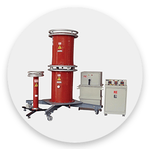
High Voltage Testers for AC High Voltage Testing.
High Voltage Testing Equipment for AC High Current Testing.
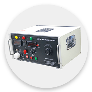
High Voltage Testing Equipment for DC High Current Testing.
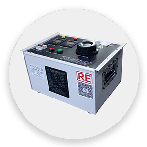
High Voltage Testing Equipment for DC Electrical Machines.
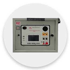
High Voltage Testing Equipment for Customized Applications and Procedures.
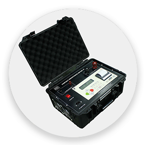
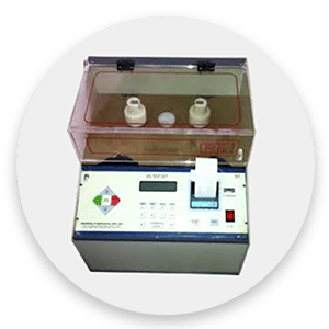
Transformer oil BDV test set, transformer oil BDV test kit