The Induced Over Voltage Test Set or D.V.D.F / I.O.V.W is designed to test the insulation strength between turns and other components within transformers. It is designed as per the BIS and other standard specifications.
How does it work?
During this test, double the standard voltage is applied to the low-tension (L.T.) terminals for a duration of one minute, with an increased frequency used to limit the magnetizing current.
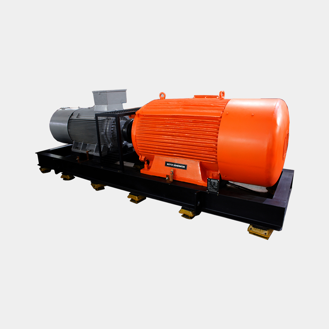
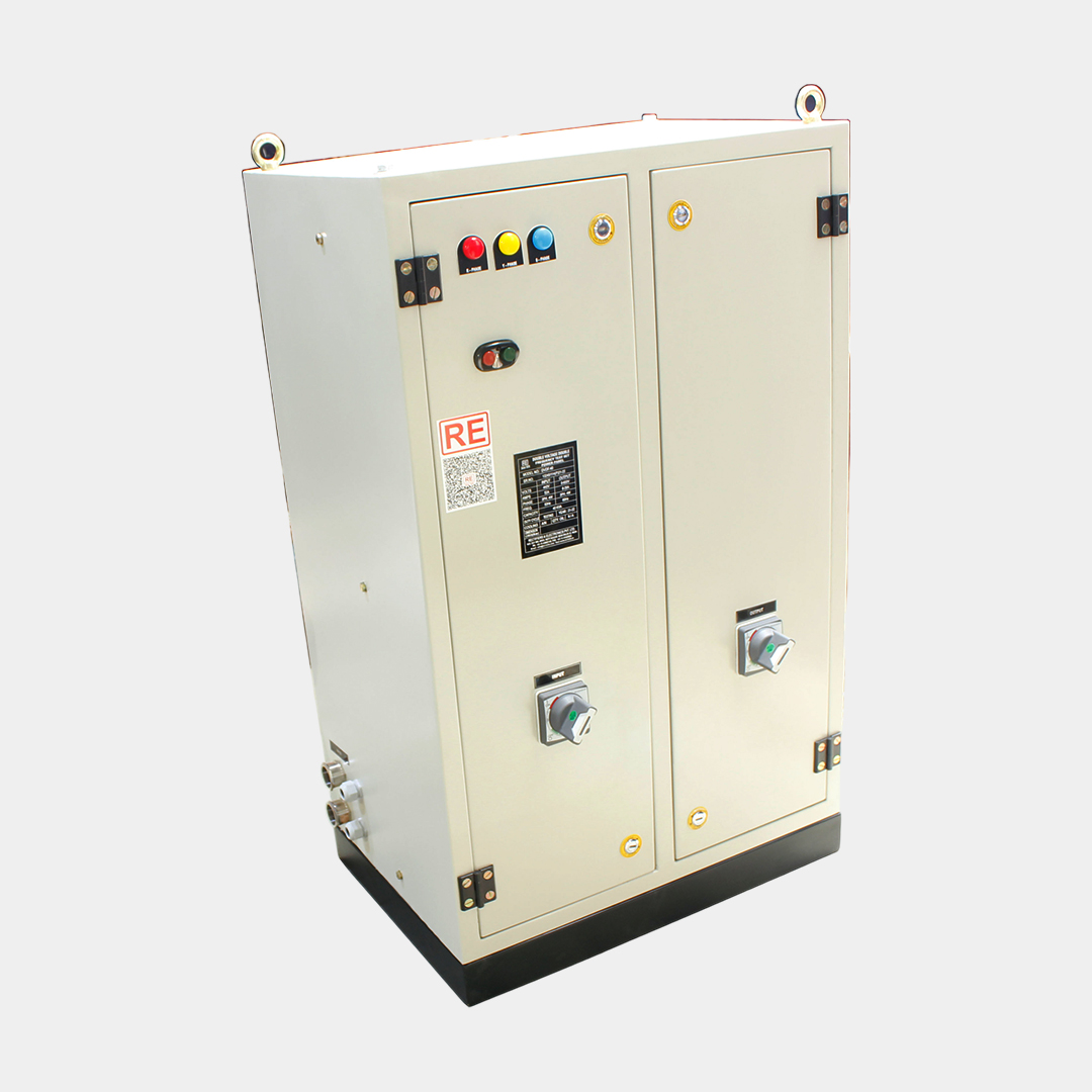
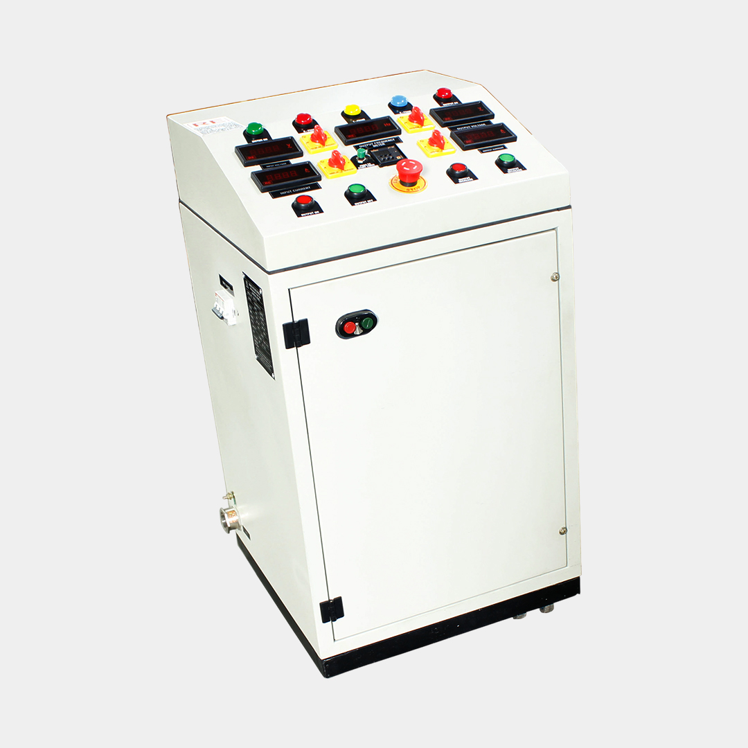
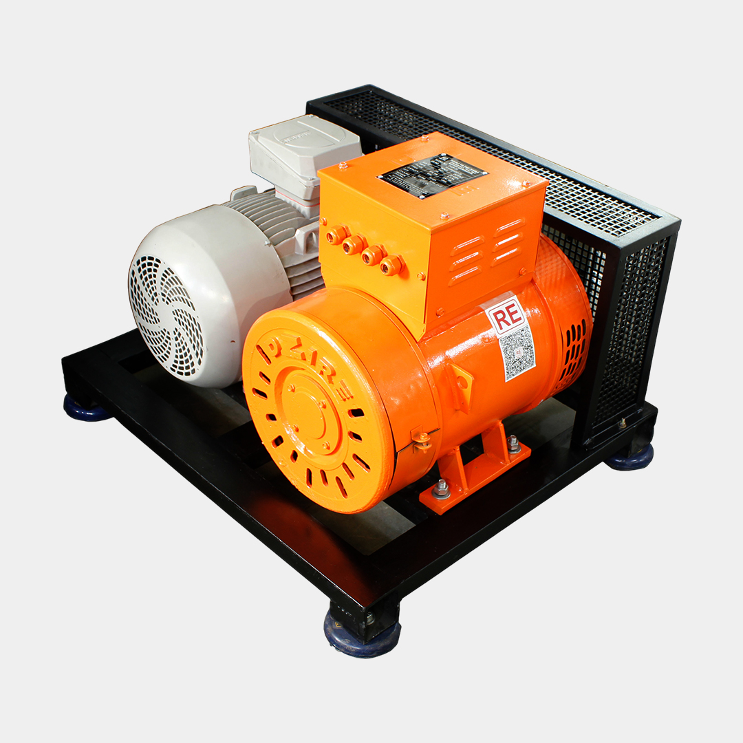
This setup is a mechanically integrated unit that includes a motor and generator, along with a power and control panel to manage the output voltage. The control panel is equipped to handle motor startup, regulate the generator’s output, and measure the voltage and current for all three phases on both the input and output sides. Additionally, it features a protection circuit to ensure safe operation.
Standard Accessories
Interconnecting Control Cables having details below:
Optional Accessories
| Parameter | Description | |
| 1 | Maximum Capacity | Up to 10 MVA |
| 2 | Input Voltage | 400V 3-phase / 11kV 3-phase beyond 1MVA |
| 3 | Output Voltage | 1000V up to 1mVA 11kV up to 10 MVA |
| 4 | Output Frequency | 200HZ 50 to 200HZ |
| 5 | Protection | Overvoltage protection Overcurrent Protection Overload Protection Overspeed Protection Frequency Feedback |
| 6 | Generator | Brushless Slip Ring type |
| 7 | Motor | Induction type |
| 8 | Rated RPM | 1500 |
| 9 | PD Level | Induction Generator – NA Brushless Generator – less than 2pC |
| 10 | Mounting | On Vibration pads |
| 11 | Metering | Digital |
| 12 | Control | Manual Control Digitized Panel PLC Based System |
| 13 | Motor Starting | DOL up to 10HP Star Delta Starter up to 75 HP Soft Starter up to 500HP AC drive beyond 500HP |
| 14 | Motor – Generator Coupling | Up to 10 KVA – Spring Loading Self aligning After 10kVA – 100kVA – Tyre coupling Above 100KVA – Solid flange coupling |
Domestic Govt. Sales :
Mr. Gulshan Matta : 9312015657
Domestic /International Sales:
Mr. Chandan Chugh 9910962423
Mr. Vinod Bajaj 9811211479
For Service Queries :
Ms Manju : 9953909888
For Calibration:
Ms Kirti Sharma : 01143680100 (Ext. 242)
Copyright 2025 Rectifiers & Electronics Pvt. Ltd. All Rights Reserved.