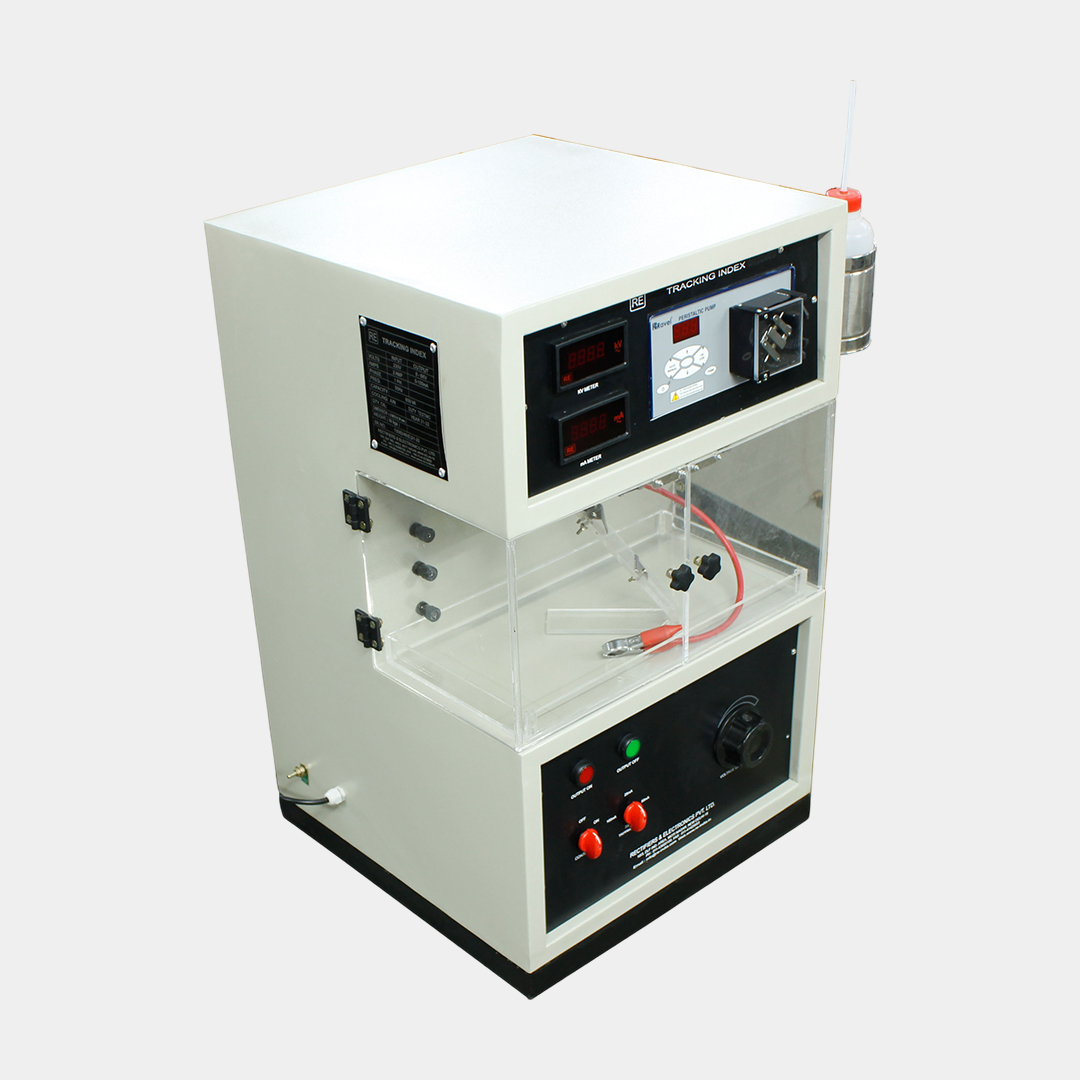
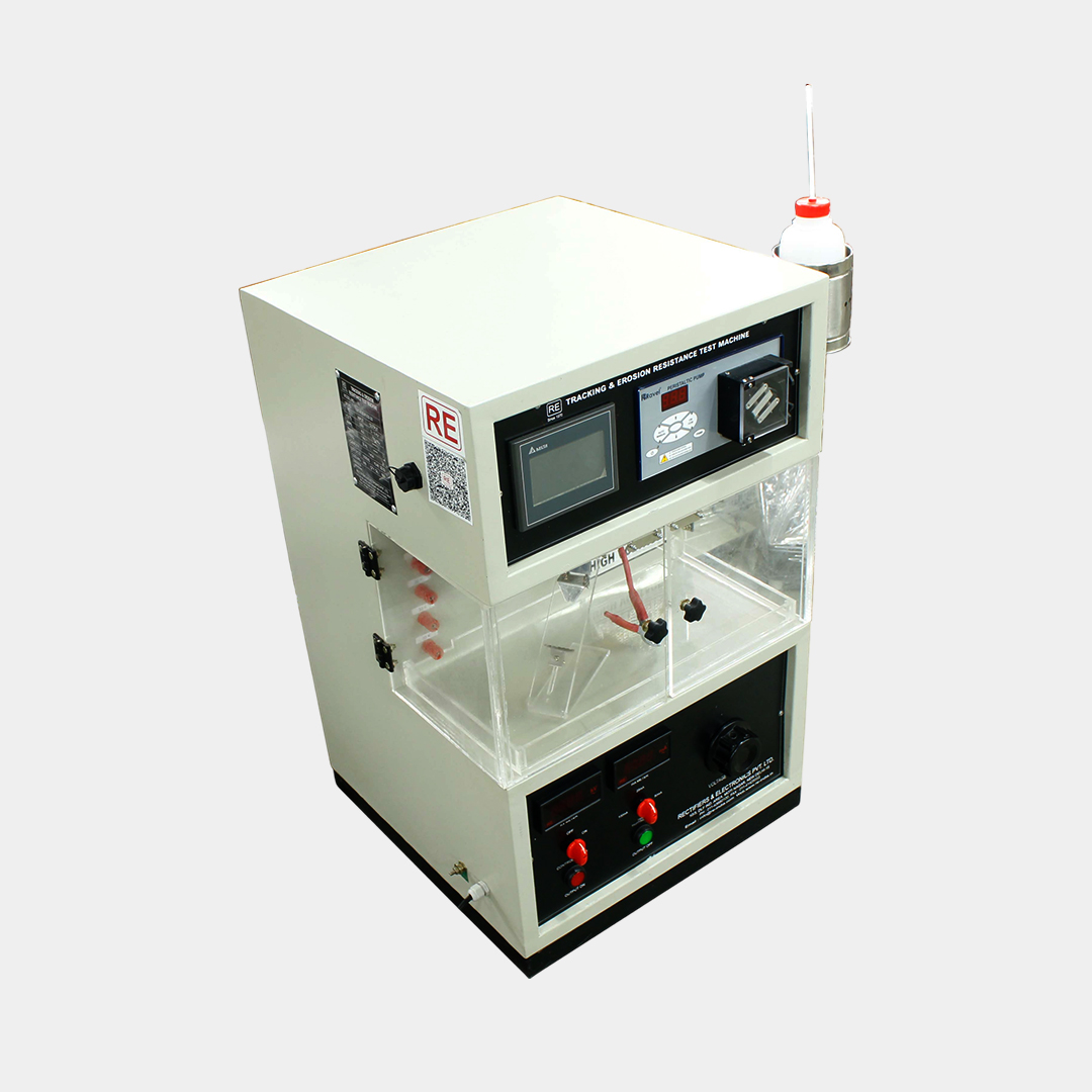
The Tracking Resistance Erosion Test Equipment is used to test how solid electrical insulating materials react to surface tracking under electrical stress, water, and contaminants from the environment.
The grading of materials based on the tracking index might differ from results obtained through other measurement methods.
However, the tracking index results themselves are not directly used to determine safe creepage distances when designing electrical equipment.
How does it work?
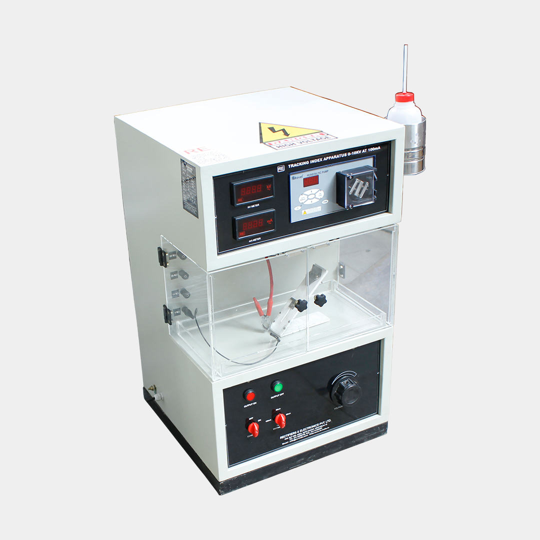
During the test, drops of an electrolyte are systematically applied to the surface of insulating materials between two electrodes, while voltage is applied. The point at which breakdown occurs across the surface correlates with the applied voltage.
The numerical voltage values corresponding to these critical breakdown points define the tracking resistance. This test emphasizes the need for prompt execution.
Moreover, the degree of comparative tracking is indicated by the number of drops required to initiate tracking at a test voltage set 10% below the critical breakdown voltage.
Standard Accessories
| Technical Specifications | ||
| Parameters | Description | |
| 1 | Input voltage | 220/ 230 Volts, Single phase 50/60 Hz. AC supply. |
| 2 | Output voltage | 0-10KV |
| 3 | Output Current | 100mA |
| 4 | Capacity | 1 KVA |
| 5 | Rating | Testing duty (Continuous). |
| 6 | Cooling | Air-cooled. |
| (Peristaltic Pump Section) | ||
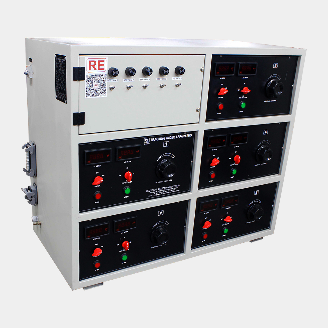
| 7 | No. of Channel | Up to Five |
| 8 | RPM | 0.01 to 9.99 |
| 9 | Flow Rate | 0.12 to 600 ml/hr |
| 10 | 1.2 to 120 ml/hr in 1 mm I.D. tubing | |
| 11 | 3.0 to 300 ml/hr in 2 mm I.D. tubing | |
| 12 | 6.0 to 600 ml/hr in 3 mm I.D. tubing | |
| Tubing | ||
| 13 | (with 1 or 1.5 mm wall thickness) | |
| 14 | Pressure | Up to 2 kg/sq.cm |
| 15 | Supply | 230 v, 50 Hz, A.C. |
| 16 | Motor | DC Stepper Motor |
| 17 | Temp. range | 0 to 50 deg. C |
Domestic Govt. Sales :
Mr. Gulshan Matta : 9312015657
Domestic /International Sales:
Mr. Chandan Chugh 9910962423
Mr. Vinod Bajaj 9811211479
For Service Queries :
Ms Manju : 9953909888
For Calibration:
Ms Kirti Sharma : 01143680100 (Ext. 242)
Copyright 2025 Rectifiers & Electronics Pvt. Ltd. All Rights Reserved.