
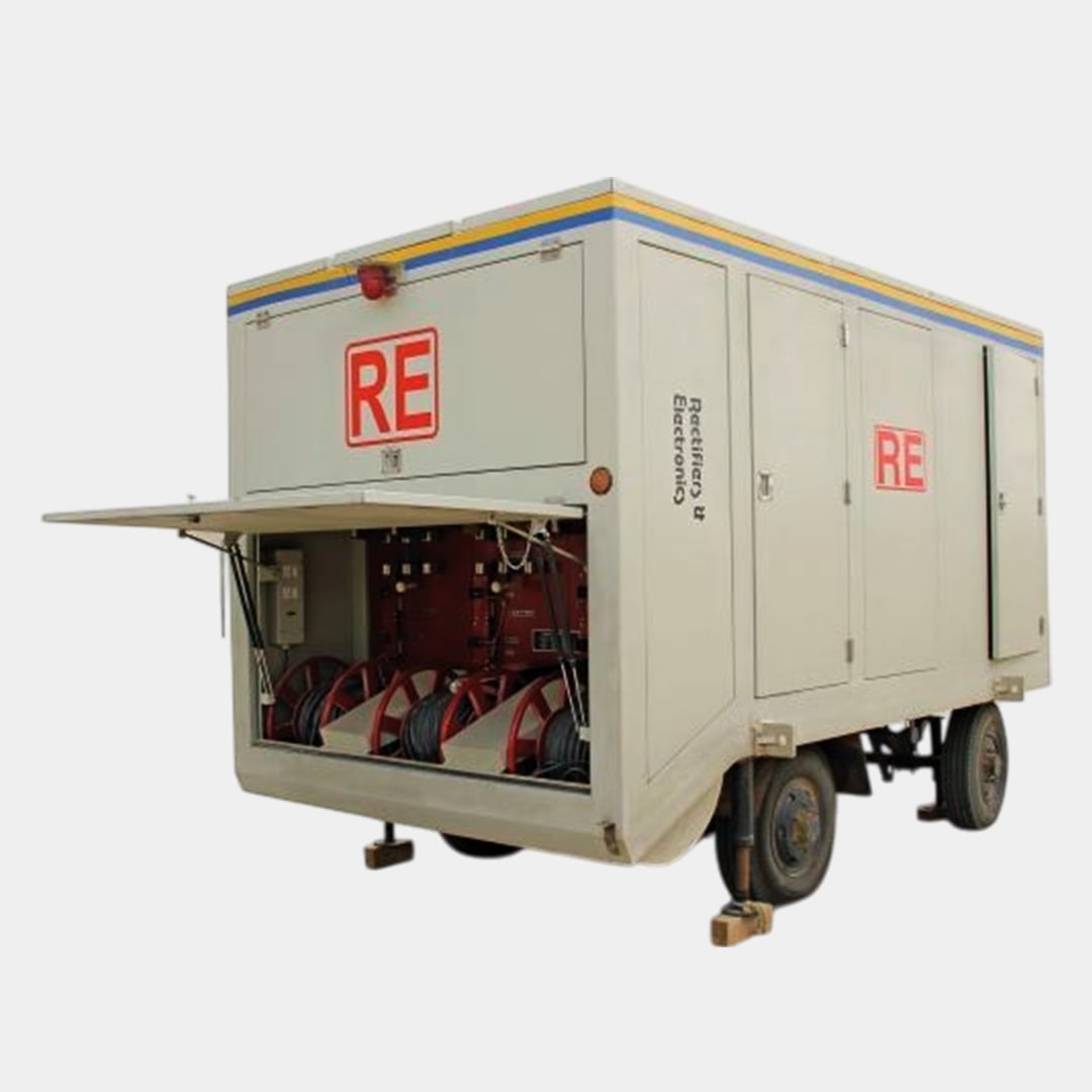
GIS Substation Testing Trolley is used to test the entire GIS substation with phantom loading. The trolley consists of a Primary current injection kit, a High Voltage kit, and a phase shifting transformer. The unit is divided into two parts one is the control area and the other is the power source area. In the control area sitting arrangements is there for two persons with air conditioning. Entry point in both the areas is separate. There is an access point from control area to power source area. The trolley is fitted with all the accessories for standard operation.
| Parameter | Description | |
| 1 | Input Voltage | 433V 50HZ / 60HZ AC Supply |
| 2 | Auxliary Voltage | 400V 3 Phase |
| 3 | Division of Complete Unit | |
| 4(i) | Control Panel | Power Source |
| All the controls for Primary Injection, High Voltage and Phase Shifting Transformer | Main Transformer for primary current injection Test Set – Up to 1000A and Open Circuit Voltage of 440V or as required | |
| For Primary Current Injection Amperemeter,Line on indicator, Main On/Off Switch for Primary Current Testing. | Auto Transformer – 250 Amp Single Phase Motorised Oil Cooled 3 Nos.or as required. | |
| For High Voltage Input ON/OFF switch, Input ‘ON’ Indicators, HT ON Push Button, HT ON Indicator, Push Buttons to increase/decrease the HT OFF Indicator, H.T Probe Set with H.T cable, KV Meter Digital with VSS,mA Meter Digital with ASS | AC High voltage up to 30kV, 200mA or as required. | |
| Phase Shifting transformer up to 200VA with Phase shift of 0-360° adjustable | ||
| 5 | Main Transformer | Shall be air cooled type. Primary winding having DCC insulation and secondary winding of bare copper strip. The unit will have provision for forced cooling. The copper busbar shall be of electrolyte grade. The neutral shall also be brought outside.The design of Main Transformer will be such that can generate 1000 Amps. In case of need, each phase can be used independently. The unit shall be consist of primary switch for change from independent control to simultaneous control of all three phases |
| 6 | Regulating Transformer | Will be Motorised having limit switches. |
| 7 | Accessories and Enclosure | All the unit shall be housed in MS sheet body supported with angle iron frame. Cables : 5×50 mm 2 with connection clamps or plug, 25m 5x24mm 2 with CEE plug, 25m (120×2) mm 2 with connection clamps length 25m |
Domestic Govt. Sales :
Mr. Gulshan Matta : 9312015657
Domestic /International Sales:
Mr. Chandan Chugh 9910962423
Mr. Vinod Bajaj 9811211479
For Service Queries :
Ms Manju : 9953909888
For Calibration:
Ms Kirti Sharma : 01143680100 (Ext. 242)
Copyright 2025 Rectifiers & Electronics Pvt. Ltd. All Rights Reserved.