



| Parameters | Description | Remarks | |
| 1 | Maximum Capacity | LT and HT Motor | |
| 2 | Input Supply Voltage | 220/230V, 50/60HZ or 380/400V, 50/60HZ Supply | |
| 3 | Frequency | 50HZ/60HZ | |
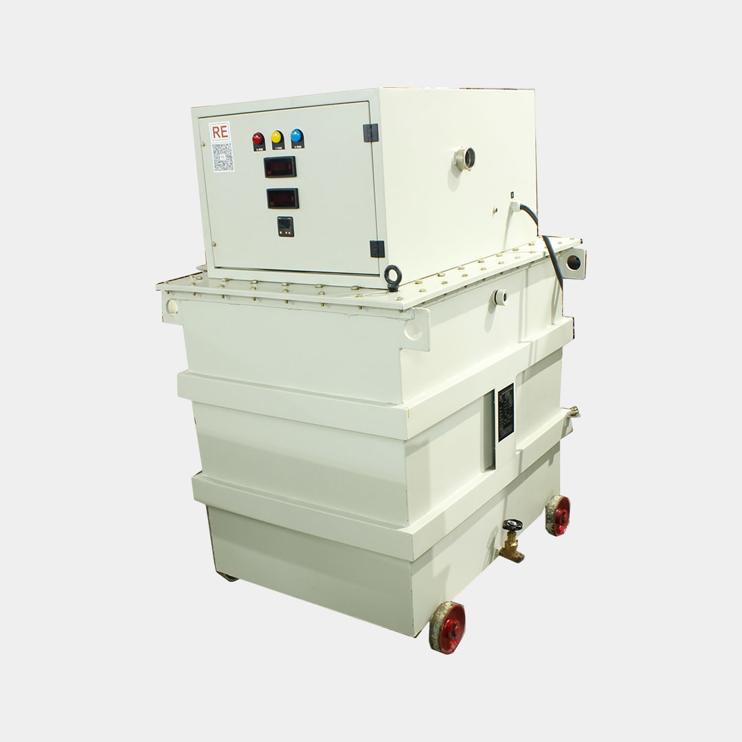
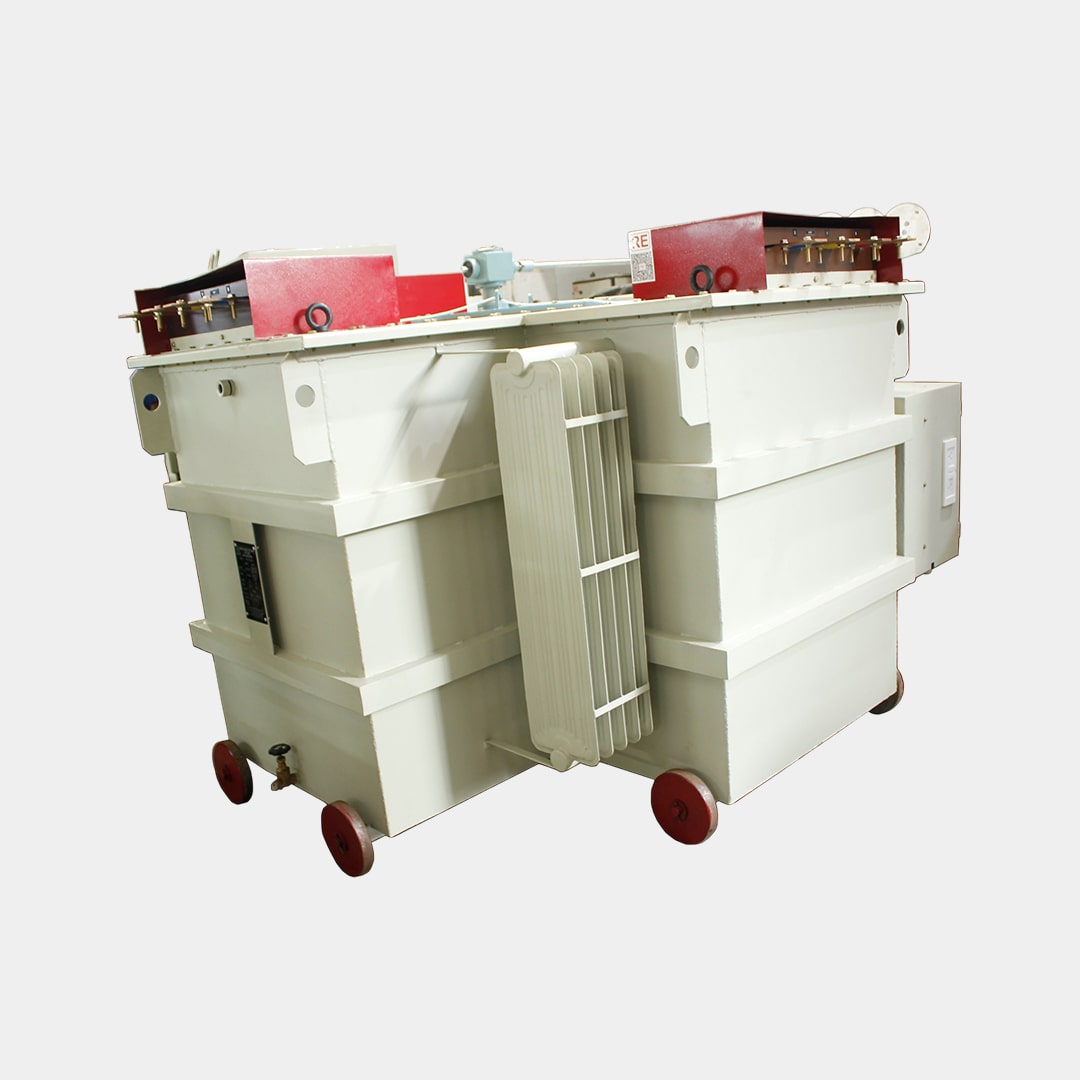
| 4 | Output AC Supply | Up to 11000V with taps as required | Taps are used for Testing AC and DC motors |
| 5 | Duty Cycle | Continuous | |
| 6 | DC Supply | Up to 1000V continuous | |
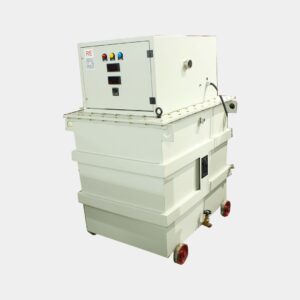
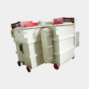
| 7 | Main Transformer | Will be provided with taps as required | |
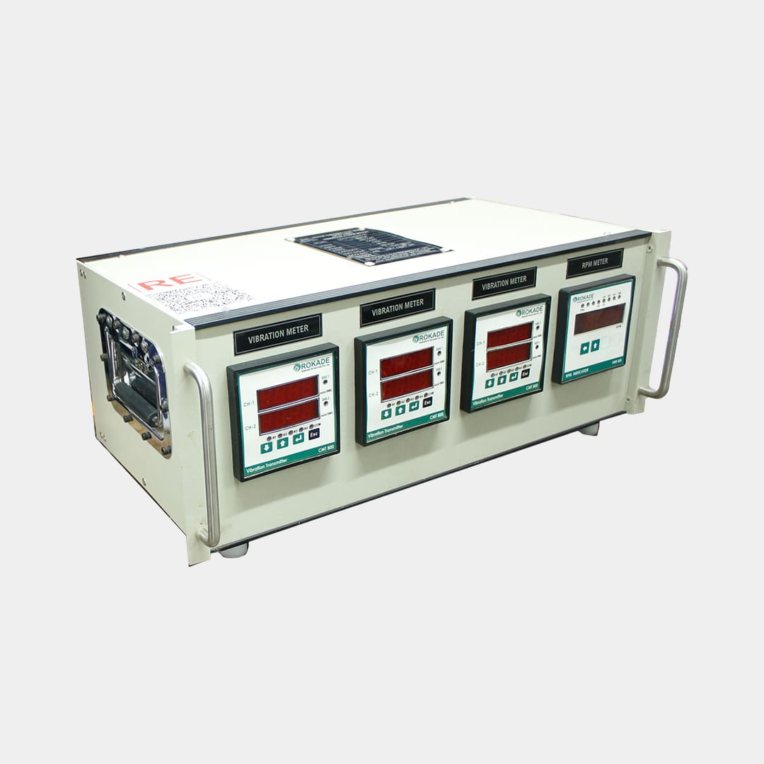
| 8 | Parameters to Be Tested | Rated Speed, Rated Voltage, Over speed and over voltage | |
| 9 | Operation | Manual as well as automatic | |
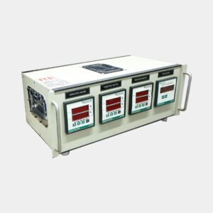
| 10 | PLC function | System On/Off – Tap Selection – Voltage Inc/Dec – Ground Fault Protection – Overload Protection – Meter Reading – Data Output – Remote Programming / Trouble Shooting Through Modem Connectivity – Testing Report Printout | |
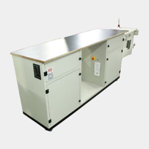
| 11 | Manual Function | Main Breaker With Indicator – Control Breaker With Indicator – Cooling Fans Breaker With Indicator – Hv On/Off Pushbuttons With Indicator – Output Tap Selection Pushbuttons. -. Raise/Lower Voltage Ramp Controls Pushbuttons With Indicators. – Off-Zero Indicator – Key-Switch Interlock For Hv Tap Switches – Emergency Off Mushroom Switch – Security Circuit Interlock Open Indicator – Ground Fault Interrupt With Reset Pushbutton And Indicator – Regulator Overload With Reset Pushbutton And Indicator. | |
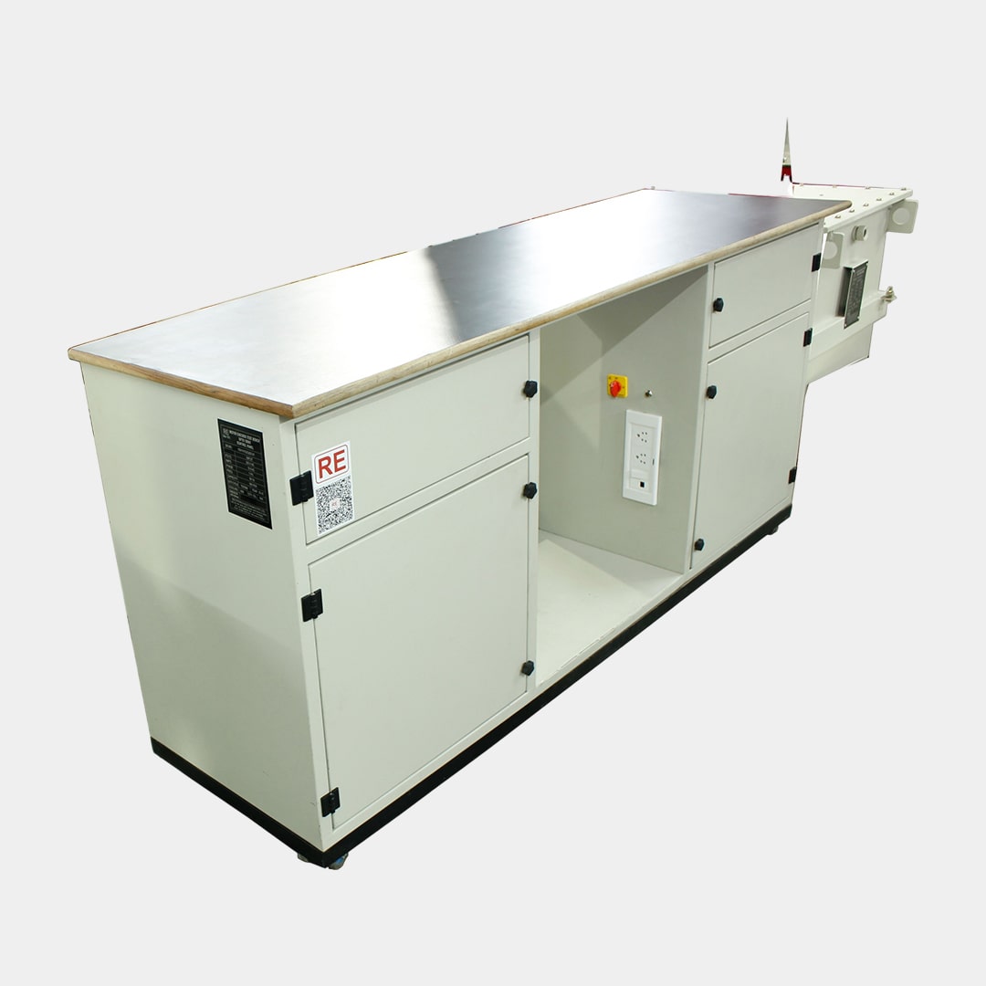
| 12 | Design Features | Main Power Circuit Breaker. – Control Power Circuit Breaker. – Motorized Dimmer/Variac Is Used For Varying The Output Voltage On Each Tap From Zero To Full Tap Voltage. – CT Range Selection Through Plc/Push Button. – PT Range Selection Through PLC Push Button – Motorized Tap Selector – Crane Lifting Provisions. – Test Voltage+ Raise / Lower Pushbuttons. – Field On / Off Pushbuttons. – Variable Field Supply – Remote Desk – Remote Programming / Trouble Shooting Through Modem Connectivity. 13.Panel Ip55 | |
| 13 | Safety Protections | Emergency Off Mushroom Switch. – Zero-Start Interlocks With Output Voltage Zero Indicator Lamp. – Five Amp Ground Fault Detection Circuit With Indicator and Reset. – External Interlock Provision. – Key Switch Interlock For High Voltage Taps. – Voltage And Current Overload Protection Circuit. – Field Under Current Protection With By Pass – Field Loss Indicator Lamp. – Armature / Field Interlock To Prevent Dc Armature Voltage From Being Applied Before Field. – External Interlock Provision With Indicator Lamp For Connecting Safety Gates. – Flashing Red Warning Light On Top Of Remote Desk. Standard Measurement Features For AC/DC Motor Test System. |
Domestic Govt. Sales :
Mr. Gulshan Matta : 9312015657
Domestic /International Sales:
Mr. Chandan Chugh 9910962423
Mr. Vinod Bajaj 9811211479
For Service Queries :
Ms Manju : 9953909888
For Calibration:
Ms Kirti Sharma : 01143680100 (Ext. 242)
Copyright 2025 Rectifiers & Electronics Pvt. Ltd. All Rights Reserved.